How the projection vector is calculated
Triangulation of a polyline set makes use of a calculated projection vector. You find the dip and azimuth of the projection vector in the Projection Dip and Projection Azimuth columns on the Triangulation Settings form, but they can be overwritten if desired.
In the triangulation process, the vector is used as follows:
- For each polyline set, an 'optimal flat plane' is determined (see image below).
- All nodes are projected onto that plane, after which they are triangulated.
- The triangles are projected back onto the original nodes, forming the triangulated surface.
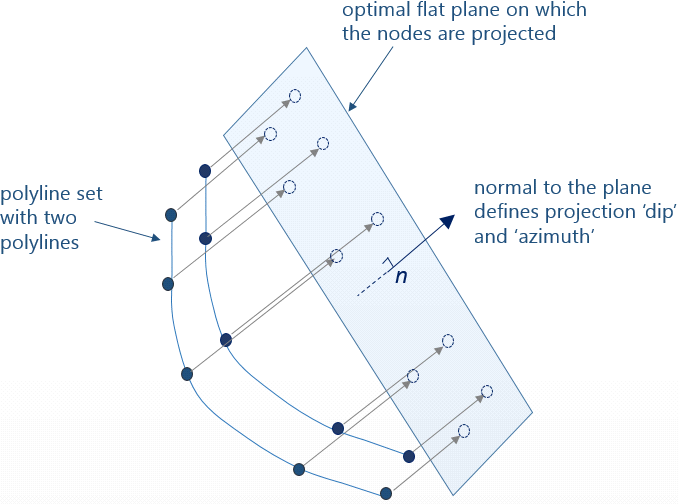
Schematic figure showing how the dip and azimuth of the projection vector are based on the normal n to the 'optimal flat plane'. click to enlarge
In some occasions the auto-detected projection dip and azimuth results in poor triangulation results, such as flat triangles, folded edges, gaps, etc. This is typically the case when strong curvatures in the surface are pointed in the same direction as the projection vector, see schematic image (in 2D) below. In that case it is recommended to override the auto-detected projection values by selecting User Defined (in the 'Projection Type' column) and manually enter the Projection Dip and Projection Azimuth in the relevant columns of the Triangulation Settings form.
You can use the Triangulate form to visually determine an alternative projection vector in the 3D View. To do this, open the Triangulate form (prepare > Post-Processing Tools > Polyline Set Tools > Triangulate), select the model at the top and on the Objects tab, select the relevant polyline set. Go to the Settings tab and check the 'Projection normal settings' checkbox, which will open the Dip and Azimuth(GN) entry fields. Now rotate the polyline set (for which you want to determine the projection vector) in the 3D View such that it is optimally visible and click Set from view, which will enter the dip and azimuth of the 'current' projection vector in the entry fields (with 'current' projection vector the imaginary line between your eye and the (orthogonal) polyline set in the 3D View is meant). Read the dip and azimuth values and type them in the relevant columns of the Triangulation Settings form.
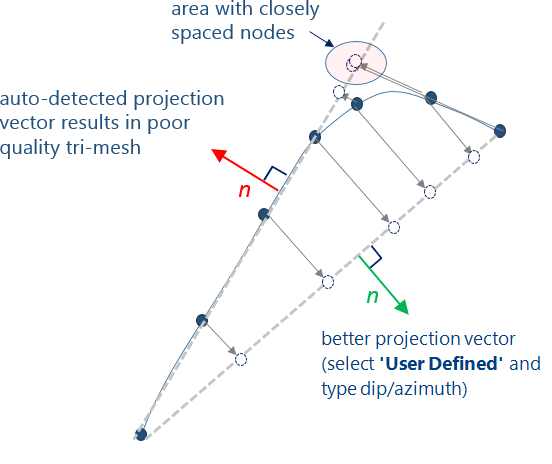
Schematic figure in 2D of a situation where the automatically calculated projection vector leads to a poor quality tri-mesh with flat triangles. click to enlarge